The modeling configuration of Elipse Power objects in an application must be performed according to the next procedures.
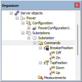
1.Create the structure of Discrete and Step Commands of the application on the Substation folder, according to the next figure.

Configuration of Commands
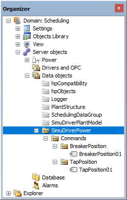
2.The SimuDriverPower folder contains Internal Tags that simulate the use of a Driver together with Discrete and Step Commands from Elipse Power. Create these objects according to the next figure.

Simulation structure
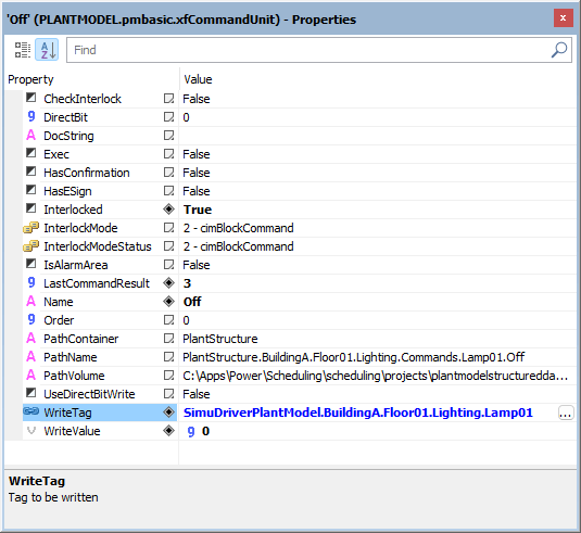
3.For these Internal Tags to receive information, users must link the WriteTag property of Discrete and Step Commands with their respective Tags from the SimuDriverPower folder.

Configuration of properties of Commands
NOTE |
Users must create a number of Command Units according to the number of possible Discrete and Step Commands and their respective command values configured in the WriteValue property. |
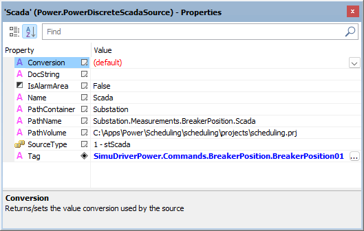
4.The objects from the Measurements folder receive values from Commands. Link the objects from this folder with their respective Internal Tag from the SimuDriverPower folder, according to the next figure.

Configuration of return values of Commands