1.First, select the Switch ![]() and insert a new Switch on the drawing area.
and insert a new Switch on the drawing area.

Inserting Switch 29-02
2.On its Properties List, change this Switch's name to "29-02".
3.Near Switch 29-02, insert a new Switch and change its name to "29-04".

Inserting Switch 29-04
4.For an easier drawing, activate the grid ![]() and the alignment of elements to the grid
and the alignment of elements to the grid ![]() . Switches must be aligned to the grid, as shown on the next figure.
. Switches must be aligned to the grid, as shown on the next figure.
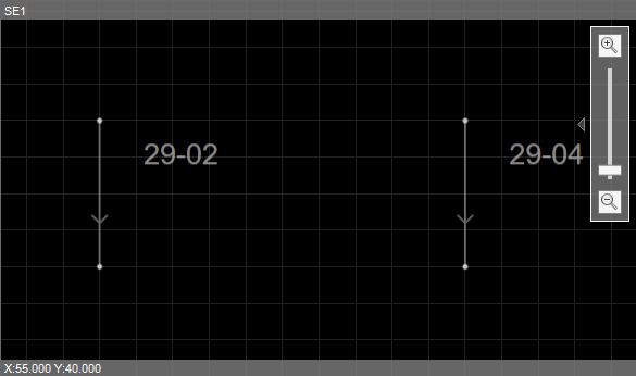
Activating grid alignment
5.The Lock/Unlock ![]() option helps when creating several objects at once. Select this option and then select the Breaker
option helps when creating several objects at once. Select this option and then select the Breaker ![]() .
.
TIP |
To create several objects at once, users can also use the CTRL key. |
6.Insert five Breakers in this model and configure each object's name as "52-01", "52-02", "52-03", "52-04", and "52-05". This model should look like the following figure.

Inserting Breakers
7.Below Breakers 52-03, 52-04, and 52-05, insert three new Switch Fuses. Configure their names as "29-08", "29-10" e "29-12". This model should look like the following figure.

Inserting Switches
8.Select the Busbar ![]() and insert a Busbar between Switch Fuses 29-02 and 29-04 and Breaker 52-01. Rename this Busbar to "BAR_138KV".
and insert a Busbar between Switch Fuses 29-02 and 29-04 and Breaker 52-01. Rename this Busbar to "BAR_138KV".

Inserting Busbar BAR_138KV
9.Insert a new Busbar between Breaker 52-02 and Breakers 52-03, 52-04, and 52-05. Rename it to "BAR_13_8KV", as shown on the next figure.

Inserting Busbar BAR_13_8KV
10.Select the Two-Winding Transformer ![]() and insert a Two-Winding Transformer between Breakers 52-01 and 52-02.
and insert a Two-Winding Transformer between Breakers 52-01 and 52-02.

Inserting Transformer TR-01
11.Rotate the Transformer object, so that its Terminal 1 remain on top. Rotation can be performed by clicking the rotation button ![]() on the upper left corner of this object, or by selecting an object and pressing the R key. This model should look like the following figure.
on the upper left corner of this object, or by selecting an object and pressing the R key. This model should look like the following figure.

Rotating a Transformer
12.On Transformer's Properties list, change the following properties:
•BaseVoltage1: 138
•BaseVoltage2: 13.8
•ConnectionType1: 0 - ctDelta
•ConnectionType2: 1 - ctWyeGrounded
•Name: TR-01
13.Select the Connector ![]() and connect Terminals of all devices.
and connect Terminals of all devices.
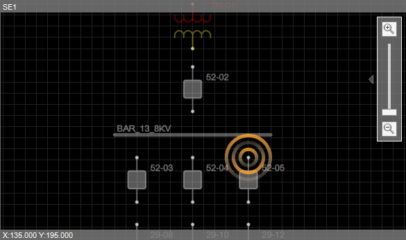
Inserting a Connector
14.After connecting all objects, this Substation should look like the following figure.

Substation after connecting all devices
15.To energize this Substation, let's use a Generator object. Select the Generator ![]() and click the drawing area near Switch Fuse 29-02.
and click the drawing area near Switch Fuse 29-02.
16.Change Generator's BaseVoltage property to "138" and connect it to Switch Fuse 29-02.

Inserting Generator G1
17.To break a line and perform a 90° curve, users must insert a Vertex. Select the Vertex ![]() and click the Connector. A Vertex can also be created by pressing the CTRL key and clicking a Connector. Drag this Vertex to any position.
and click the Connector. A Vertex can also be created by pressing the CTRL key and clicking a Connector. Drag this Vertex to any position.

Inserting a Vertex on Generator G1
18.Select the Generator ![]() again and insert a new Generator near Switch 29-04. Change Generator's BaseVoltage property to "138kV" and connect it to Switch Fuse 29-04.
again and insert a new Generator near Switch 29-04. Change Generator's BaseVoltage property to "138kV" and connect it to Switch Fuse 29-04.

Inserting Generator G2
19.Rename these Generators as "G1" and "G2".
20.Select the Load ![]() and insert a new Load near Switch 29-08. Rename it to "L1" and connect it to Switch 29-08.
and insert a new Load near Switch 29-08. Rename it to "L1" and connect it to Switch 29-08.
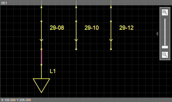
Inserting Load L1
21.Insert another two Loads, renaming them as "L2" and "L3" and connecting them to Switches 29-10 and 29-12.
22.Let's organize the sets of Loads, Switches, and Breakers into Bays. While pressing the SHIFT key, click objects 52-03, 29-08, and L1 in sequence. Another way to select multiple objects is by clicking the drawing area and dragging the mouse pointer, thus forming a selection area.
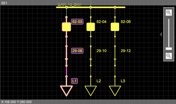
Selecting Loads, Switches, and Breakers
23.Use the Create Bay with selected device(s) ![]() option to create "Bay1".
option to create "Bay1".

Creating a Bay with all selected devices
24.Repeat the previous step to create "Bay2", by grouping objects 52-04, 29-10, and L2, and "Bay3", by grouping objects 52-05, 29-12, and L3.
25.At the end of this process, this electrical model should look like the following figure.
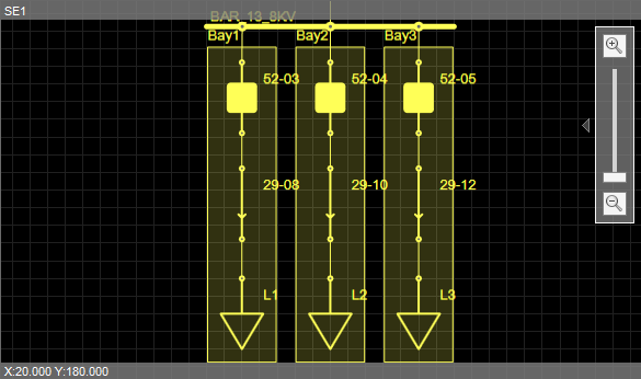
Substation's final result
26.Leave a space at the bottom of this diagram, below all Loads. This is where some screen Displays are going to be placed further. Click the lower right corner and drag the mouse pointer down, increasing the size of this drawing area. Another option is reconfiguring the CanvasBottom property with a higher value.

Adding a space under the diagram

Substation's CanvasBottom property