The Electrical Modeler contains toolbars that allow creating new electrical elements, as well as navigating through the modeled system. The available toolbars are Alignment and Grid, General, Bays and Transmission Lines, and Elements. A description of all options on these toolbars is available on the next tables.
Available options on Alignment and Grid toolbar
Option |
Description |
|---|---|
Activate or Deactivate Grid |
Activates or deactivates a grid in the modeling environment |
Activate or Deactivate Align to Grid |
Activates or deactivates the alignment of objects relative to the grid |
Align Left |
Aligns objects to the left |
Align Right |
Aligns objects to the right |
Align Top |
Aligns objects by the top |
Align Bottom |
Aligns objects by the bottom |
Align Horizontal Center |
Aligns objects horizontally by the center |
Align Vertical Center |
Aligns objects vertically by the center |
Align to Grid |
Aligns objects to the grid |
Available options on General toolbar
Option |
Description |
|---|---|
Back |
Returns to the previous element in the navigation history (BACKSPACE) |
Forward |
Goes to the next element in the navigation history (ALT + Right arrow) |
System Diagram |
Shows model's System level |
Select |
Enables the selection mode |
Organize Diagram Automatically |
Groups elements symmetrically, to help visualization and browsing |
Locate Element |
Allows locating an element (CTRL + L). This search is performed by the name of an element, as well as by its partial name, displaying a list with all elements found. When clicking OK or when selecting an element on this list, this element is selected on the Electrical Model. NOTE: The search for elements only considers the name of an element, and not its full path |
Show or Hide Description |
Shows or hides the name of devices on the modeling screen |
Area Zoom |
Applies a zoom to a specific area |
Fit |
Fits the diagram to the drawing area (CTRL + 5 or CTRL + CLEAR). NOTE: The shortcut key for this option, on the keypad, is available only when the NUM LOCK option is disabled |
Drag |
Allows moving the drawing area |
Cable Editor |
Opens the Cable Editor window used on Feeders |
Manage Schematic Views |
Allows creating or removing Schematic Views |
Show Schematic Views |
Shows or hides Schematic View's thumbnails available on the Electrical Model |
Generate Schematic Views |
Generates Schematic Views automatically. NOTE: This tool requires a specific license for its usage |
Acknowledge Schematic View Layout |
Acknowledges the selected Schematic View layout, which was changed by the syncing tool although the option to preserve it was selected |
Available options on Bays and Transmission Lines toolbar
Option |
Description |
|---|---|
Create Bay with Selected Device(s) |
Creates a Bay with all selected devices |
Add the Selected Devices to the Selected Bay |
Adds all selected devices to the selected Bay |
Remove Selected Device(s) from Bay |
Removes all selected devices from a Bay |
Create Transmission Line with the Selected Line Segment(s) |
Creates a Transmission Line with the selected Line Segments |
Add the Selected Line Segment(s) to the Selected Transmission Line |
Adds all Line Segments to the selected Transmission Line |
Remove Selected Line Segment(s) from Transmission Line |
Removes all selected Line Segments from a Transmission Line |
Available options on Elements toolbar
Option |
Description |
|---|---|
Lock or Unlock Tool |
When activated, keeps the last selected tool active |
Substation |
Inserts a Substation |
Transmission Line Segment |
Inserts a Transmission Line (L key) |
Feeder |
Inserts a Feeder |
Wind Power Plant |
Inserts a Wind Power Plant |
Photovoltaic Power Plant |
Inserts a Photovoltaic Power Plant |
Jumper |
Inserts a Jumper (J key) |
Branch |
Inserts a Branch (B key). NOTE: This element is not available to Schematic Views |
Node |
Inserts a Node |
External Node |
Inserts an External Node. NOTE: This element can only be inserted manually in Schematic Views |
Tie Node |
Inserts a Tie Node. NOTE: This element exists in Schematic Views |
Breaker |
Inserts a Breaker. NOTE: This element is not available to Photovoltaic Power Plants |
Switch |
Inserts a Switch |
Switch Fuse |
Inserts a Switch Fuse |
Two-Winding Transformer |
Inserts a Two-Winding Transformer |
Three-Winding Transformer |
Inserts a Three-Winding Transformer. NOTE: This element is available to Substations and Photovoltaic Power Plants and is not available to Feeders and Wind Power Plants |
Load |
Inserts a Load. NOTE: This element is only available to Substations |
Generator |
Inserts a Generator. NOTE: This element is available to Substations and Feeders and is not available to Wind Power Plants and Photovoltaic Power Plants |
Reactor |
Inserts a Reactor. NOTE: This element is available to Substations and Feeders and is not available to Wind Power Plants and Photovoltaic Power Plants |
Capacitor |
Inserts a Capacitor. NOTE: This element is available to Substations and Feeders and is not available to Wind Power Plants and Photovoltaic Power Plants |
Busbar |
Inserts a Busbar. NOTE: This element is only available to Substations |
Distribution Transformer |
Inserts a Distribution Transformer. NOTE: This element is only available to Feeders |
Recloser |
Inserts a Recloser. NOTE: This element is not available to Photovoltaic Power Plants |
Voltage Regulator |
Inserts a Voltage Regulator. NOTE: This element is available to Substations and Feeders, and it is not available to Wind Power Plants and Photovoltaic Power Plants |
Wind Turbine |
Inserts a Wind Turbine. NOTE: This element is only available to Wind Power Plants |
Weather Station |
Inserts a Weather Station. NOTE: This element is available to Wind Power Plants and Photovoltaic Power Plants and it is not available to Substations and Feeders |
Photovoltaic Array |
Inserts a Photovoltaic Array. NOTE: This element is available to Photovoltaic Power Plants |
Inverter |
Inserts an Inverter. NOTE: This element is only available to Photovoltaic Power Plants |
Junction Box |
Inserts a Junction Box. NOTE: This element is only available to Photovoltaic Power Plants |
Direct Current Jumper |
Inserts a Direct Current Jumper. NOTE: This element is only available to Photovoltaic Power Plants |
Direct Current Branch |
Inserts a Direct Current Branch. NOTE: This element is only available to Photovoltaic Power Plants |
Direct Current Node |
Inserts a Direct Current Node. NOTE: This element is only available to Photovoltaic Power Plants |
Convert Branch to Connector |
Converts the selected Branches to Connectors |
Convert Connector to Branch |
Converts the selected Connectors to Branches |
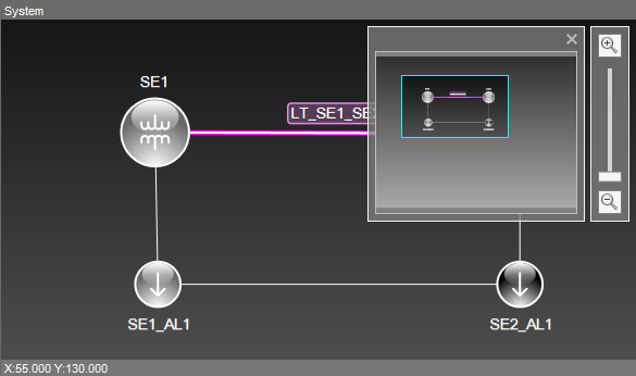
In addition to toolbars, the Electrical Modeler contains an auxiliary zoom tool, called Viewfinder. This tool makes it easy to locate a portion of the Electrical Model when it is not completely visible on the drawing area.

Viewfinder tool
There are still tools available on the drawing area, when one or more objects are selected.
Available options on the drawing area
Option |
Description |
|---|---|
Rotate |
Allows rotating the selected objects in 45-degree steps |
Resize |
Allows resizing the selected objects |
Move Busbar |
Allows moving the edges of Busbars, thus changing the size and slope angle of these objects |
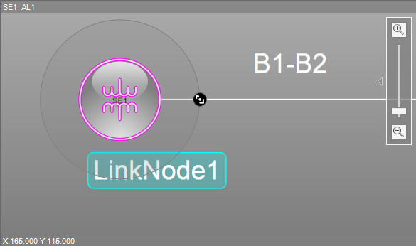
When moving the mouse pointer over an object, it is highlighted. If the object contains one or more Terminals, they are identified.

Highlighted object