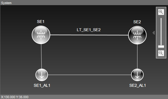
The most comprehensive level for viewing and editing available in the Electrical Modeler is the System level, where users can create Substations, Feeders, and other elements that compose a wider vision of an electrical system, in addition to define connections among these elements. Then, to edit Substations and Feeders created, double-click the desired object. This screen can also be accessed by clicking System Diagram ![]() , when users are at another level of edition, such as a Substation or Feeder. All properties of this object can be found on Elipse Power Reference and Scripts Manual.
, when users are at another level of edition, such as a Substation or Feeder. All properties of this object can be found on Elipse Power Reference and Scripts Manual.

System diagram
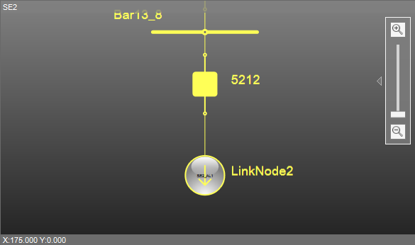
When users perform a connection between a Substation and a Feeder at System level, this automatically creates an External Node object inside each element: an External Node inside the Substation that represents the Feeder and an External Node inside the Feeder that represents the Substation. The same occurs if this connection is between two Substations or two Feeders. The next figure represents the modeling of Substation SE2. On it users can see objects of type External Node to represent Substation SE1 (LinkNode1) and to represent Feeder SE2_AL1 (LinkNode2).

Representation of Feeders