After finishing the system modeling, let's create a Schematic View to simplify the operation Screen.
1.Click Show Schematic Views ![]() .
.
2.Click Manage Schematic Views ![]() .
.
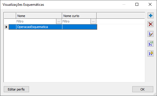
3.On the window that opens, create a new Schematic View named "SchematicOperation", according to the next figure.

Schematic Views window
4.Go back to the system diagram and drag the next devices to the Schematic View just created.
•Breaker 5201 from Substation SUB01
•Breaker 5201 from Substation SUB02
•Reclosers RL01 and RL02 from Feeder FE01
•Link Node representing Substation SUB01, located in Feeder FE01
•Recloser RL03 from Feeder FE02
•Link Node representing Substation SUB02, located in Feeder FE02
5.Add a Tie Node ![]() in the following locations:
in the following locations:
•Below Terminal 2 of Breaker 5201 from Substation SUB01
•Below Terminal 2 of Breaker 5201 from Substation SUB02
•Between Terminal 2 of Recloser RL02 and Terminal 2 of Recloser RL03
6.By using a Jumper ![]() , interconnect all devices.
, interconnect all devices.
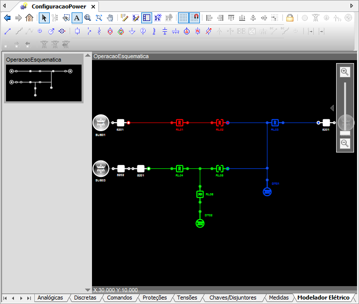
7.By the end of the configuration, the Schematic View must be similar to the next figure.

Resulting Schematic View