After configuring the Driver and importing all Tags, the next step is to link all Measurements and Commands created so far on Elipse Power's data structure to the Tags referring to the position and Commands of these two Breakers.
The first Switch to configure in the application is of a DO (Direct Operate) type, that is, it can be operated directly, without a Select command. The Switch with this type on the Simulator is Obj1CSWI1, which is going to be linked to Switch 29-02 on the application developed in this Tutorial.
1.The IEC 61850 protocol provides information about the position of a Switch using values 1 (one, close) and 2 (two, open) and, in this condition, users must create a new Conversion on Discrete Measurements' standards, to convert the value sent by a device to the values used by Elipse Power. On Power Configuration object's Discrete tab, click the *SwitchPosition standard and create a new Conversion named "IEC61850" with the values on the next figure.
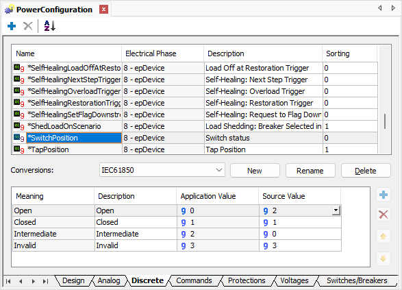
Creating a Conversion
2.After performing this standard's configuration, now let's perform a configuration on Switch 29-02. To do so, select the SwitchPosition Measurement on Measurements folder of Switch 29-02. Configure the following property of this Measurement:
•MeasurementType: *SwitchPosition
3.As we are going to work with a Tag from IEC 61850 Driver, we must create a SCADA-type source. To do so, right-click the Measurement SwitchPosition and select the Add - Scada option. Next, change the ActiveSource property of that Discrete Measurement to Scada.
4.Configure the Conversion property of SCADA source to IEC61850, created previously.
5.Link the SCADA source of Measurement SwitchPosition to Tag IEC61850.Obj1CSWI1.ST.Pos.stVal. This Link is performed in the source's Tag field, and the path referring to the I/O Tag can be retrieved using the AppBrowser or using Tag's PathName property.
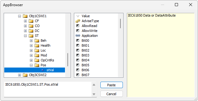
stVal Tag
6.After configuring the position Measurement of Switch 29-02, let's create a position Command. The first step is to create a new Conversion referring to the type of Switch (DO) on Command's standards. To do so, on Power Configuration object's Commands tab, select the *SwitchPosition standard and create a new Conversion named as "IEC61850_DO", changing only the values on the Operate Feedback column. Device's feedback returned by IEC 61850 protocol for an Operate command successfully performed is 5 (five), therefore users must change the value of the Operate Feedback column to 5 (five) on Conversion Open, as well as on Conversion Close.
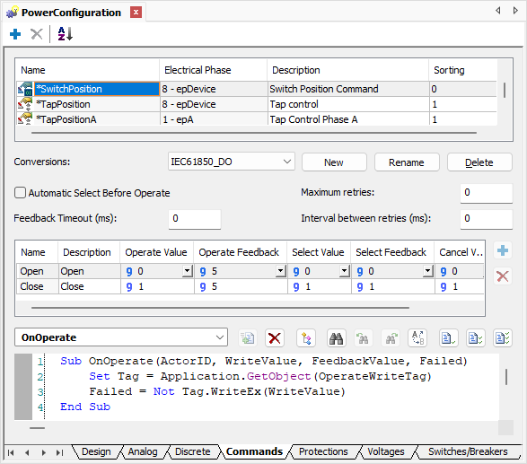
New Conversion
7.Right-click the Switch 29-02 and select the Add - Commands. option. Add a Discrete Command on folder Commands and configure the following properties of this object:
•Name: cmdSwitch
•CommandType: *SwitchPosition, on the Type column
•Conversion: IEC61850_DO
8.On this Switch, let's add two Command Units, one to send a command to open and another one to send a command to close. By default, a Command object already contains a Command Unit, therefore users must only create a new Unit. To do so, right-click the Command cmdSwitch and select the Insert - Command Unit option.
9.Select CommandUnit1 and change the following properties:
•Name: Open
•CommandName: Open
10.Select CommandUnit2 and change the following properties:
•Name: Close
•CommandName: Close
11.The Simulator used in this exercise contains two Switches, one of type DirectOperate and another one of type SelectBeforeOperate. In this first exercise, let's configure the Command of type DirectOperate. For these types of Switches, the Simulator provides only one Operate Tag responsible for performing the opening or closing Commands. In addition, users can use the feedback feature to check device's response regarding the Command sent. The following Tags must be linked to the OperateWriteTag and OperateFeedbackTag properties of Command Units Open and Close.
•OperateFeedbackTag: IEC61850.Obj1CSWI1.CO.Pos.Pos_Stat.Status
•OperateWriteTag: IEC61850.Obj1CSWI1.CO.Pos.Operate
NOTE |
These Tags, for Command Unit Open as well as for Command Unit Close, are the same. Each Command Unit contains their respective OperateWriteTag and OperateFeedbackTag properties, and they are linked exactly with the same Tags on the Driver. |
12.Execute the application together with Infotech Simulator and test this new Command.
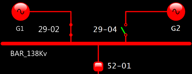
Application at run time
13.After configuring the position's Command and Measurement of Switch 29-02, let's create Analog Measurements referring to phase currents A, B, and C of Simulator's Switch Obj1CSWI1. To do so, create three Analog Measurements on folder Measurements of object 29-02 in Elipse Power's data structure, using the Insert - Analog Measurement option.
14.Rename those Measurements to "CurrentA", "CurrentB", and "CurrentC", configuring the type of these Measurements with their respective standard, as shown on the next figure.
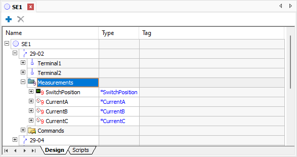
Analog Measurements
15.Create a SCADA-type source in each one of these Measurements, by right-clicking a Measurement and selecting the Add - SCADA option.
16.Change the following properties of Measurement CurrentA:
•ActiveSource: 1 - stScada
•Tag: IEC61850.[I3pMMXU1$MX$A$phsA].cVal.mag.f.Value
17.Change the following properties of Measurement CurrentB:
•ActiveSource: 1 - stScada
•Tag: IEC61850.[I3pMMXU1$MX$A$phsB].cVal.mag.f.Value
18.Change the following properties of Measurement CurrentC:
•ActiveSource: 1 - stScada
•Tag: IEC61850.[I3pMMXU1$MX$A$phsC].cVal.mag.f.Value
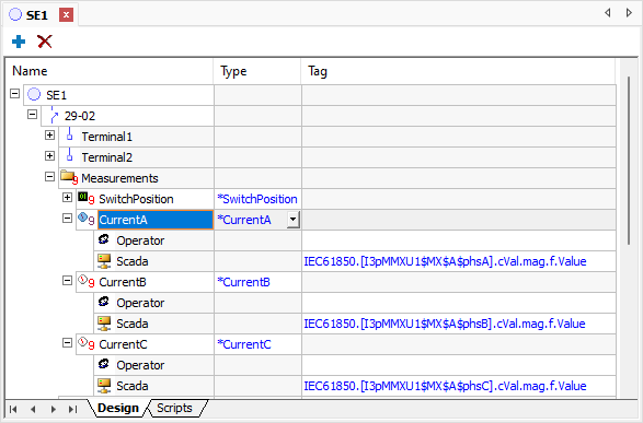
SCADA-type sources
19.Create three XPowerDisplay objects near Switch 29-02 on the operation Screen and link them to Analog Measurements CurrentA, CurrentB, and CurrentC.
20.Execute the application and check this new functionality.
The Simulator also provides an SBO (Select Before Operate) Switch, which requires a selection Command before operating. To work with this type of Command, let's create a new Conversion on Command's standards, and also perform the necessary Links, in the Command as well as in the Measurements.
21.On Power Configuration object's Commands tab, select the *SwitchPosition Command and create a new Conversion named "IEC61850_SBO". In this exercise, let's use the Automatic select before Operate option. This way, selection is performed automatically, before sending an Operate Command. As described previously, feedback returned by the IEC 61850 protocol for an Operate command performed successfully is 5 (five). For a Select command, the protocol provides a feedback of 2 (two) to inform a successful operation. Configure the value of Operate Feedback and Select Feedback columns with their respective values of 5 (five) and 2 (two) on both command actions, Open and Close.
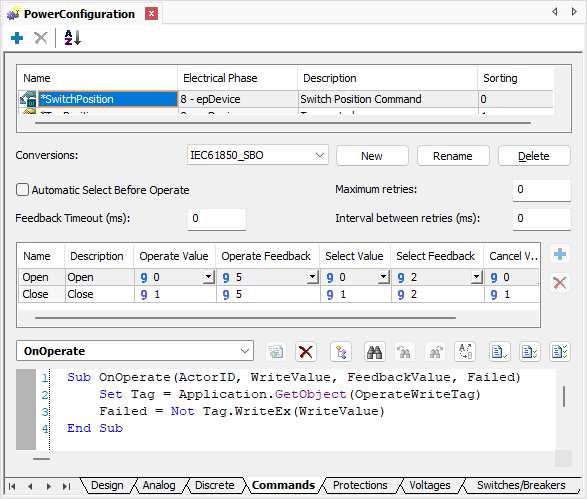
Conversion of type Select Before Operate
22.Still in Conversion IEC61850_SBO, let's create a script to perform the selection Command. By using the combo box, select the OnSelect event and click Adds script ![]() to generate this script. This script is generated automatically and users do not need to change it for a correct behavior.
to generate this script. This script is generated automatically and users do not need to change it for a correct behavior.
23.Locate the SwitchPosition Measurement on folder Measurements of Switch 29-04. Configure the following properties of this Measurement:
•MeasurementType: *SwitchPosition
24.Add a SCADA-type source by right-clicking the Measurement SwitchPosition and selecting the Add - Scada option. Next, change the following properties of this source:
•ActiveSource: 1 - stScada
•Conversion: IEC61850
25.On the SCADA Measurement, link the Tag to read the Switch's position. Click Browse Tag ![]() to search for the Tag using the AppBrowser, or copy I/O Tag's PathName property. Search for the following Tag on Driver IEC61850:
to search for the Tag using the AppBrowser, or copy I/O Tag's PathName property. Search for the following Tag on Driver IEC61850:
•Tag: IEC61850.Obj3CSWI2.ST.Pos.stVal
26.Next, let's add a position Command to Switch 29-04. Right-click this object and select the Add - Commands option. Insert a new Discrete Command on Commands folder, using the Insert - Discrete Command option, and change the following properties:
•Name: cmdSwitch_SBO
•CommandType: *SwitchPosition
•Conversion: IEC61850_SBO
Let's create two Command Units to this Command, referring to opening and closing Commands.
27.Right-click the Command cmdSwitch_SBO and select the Insert - Command Unit option.
28.Select CommandUnit1 and change the following properties:
•Name: Open
•CommandName: Open
29.Select CommandUnit2 and change the following properties:
•Name: Close
•CommandName: Close
Unlike the previous Switch, this Switch is of type Select Before Operate (SBO), that is, it requires a Select Command before an Operate Command. To do so, in addition to the Tag referring to the Operate Command, let's also link the Tag referring to the Select Command to the Command Units. Remember that we are going to use the feedback feature, in the Select Command as well as in the Operate Command.
30.The following I/O Tags must be linked to the OperateFeedbackTag, OperateWriteTag, SelectFeedbackTag, and SelectWriteTag properties of Command Units Open and Close:
•OperateFeedbackTag: IEC61850.Obj3CSWI2.CO.Pos.Pos_Stat.Status
•OperateWriteTag: IEC61850.Obj3CSWI2.CO.Pos.Operate
•SelectFeedbackTag: IEC61850.Obj3CSWI2.CO.Pos.Pos_Stat.Status
•SelectWriteTag: IEC61850.Obj3CSWI2.CO.Pos.SelectWithValue
31.Execute the application together with Infotech Simulator and test this new Command.