In Transformer TR-01, create Measurements VoltageA, CurrentA, ActivePower, and WindingTemperature and show them on Displays near the Transformer. Measurement CurrentA must be the sum of currents from Breakers 52-03, 52-04, and 52-05
1.Electrical information must be collected on device's terminal, therefore let's create the Measurements on Terminal2.
2.Right-click Terminal2 of Transformer TR-01 and select the Insert - Analog Measurement option.
3.Rename this Measurement to "VoltageA".
4.Configure the Measurement type as *VoltageA (on the combo box).
5.Select the measurement source Operator and define an initial value for it.
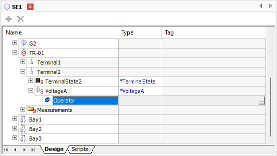
Analog Measurement
6.Repeat the previous steps to create Measurements "CurrentA", of type *CurrentA, and "ActivePower", of type *ActivePower.
7.Select Measurement ActivePower and configure the unitPrefix property with value 6 - upMega.
8.Measurement CurrentA must be the sum of currents of the other Breakers, therefore this is a calculated value. Select Measurement CurrentA and insert a source of type Calculated.
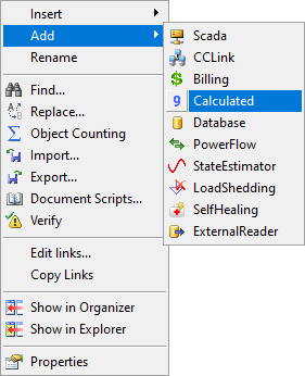
Add Calculated
9.For this measurement source, configure the Tag column with the following expression:
SE1.Bay1.[52-03].Terminal2.CurrentA.Value_
+ SE1.Bay2.[52-04].Terminal2.CurrentA.Value_
+ SE1.Bay3.[52-05].Terminal2.CurrentA.Value
10.Finally, change the ActiveSource property of Measurement CurrentA to 5 - stCalculated.
11.Information about winding temperature is a device's feature, therefore the most indicated procedure is to create this Measurement on Measurements folder, and not on a terminal. Right-click the Measurements folder and insert a new Analog Measurement.
12.Rename this Measurement to "WindingTemperature".
13.Measurement WindingTemperature does not have a standard. For this case, let's demonstrate two possible solutions:
SOLUTION 1
1.Select the Analog tab of Power Configuration object. Click Add ![]() and configure all columns as indicated:
and configure all columns as indicated:
•Name: TEN
•Electrical Phase: -1 - epNone
•Description: Winding Temperature
•Unit: °C
•Min. EU: 0 (zero)
•Max. EU: 100
•Sorting: 1000
2.Go back to the Substation and configure its Measurement type as TEN (on the combo box).
3.Define an initial value for the Operator source of this Measurement.
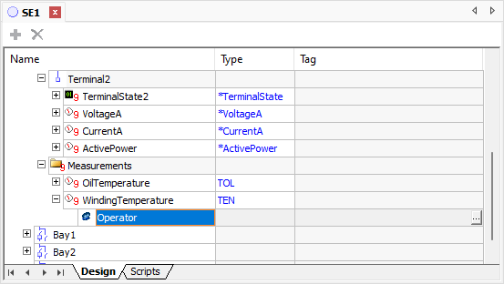
Temperature Measurement
SOLUTION 2
1.Select the Analog tab of Power Configuration object. Select the TOL standard and reconfigure it as indicated:
•Name: Temp
•Electrical Phase: -1 - epNone
•Description: Temperature {DocString}
•Unit: °C
•Min. EU: 0 (zero)
•Max. EU: 100
•Sorting: 1000
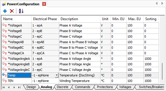
Temp Template
2.Go back to the Substation and configure the type of Measurements OilTemperature and WindingTemperature as Temp on the Type column.
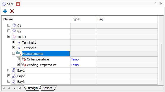
Measurement type Temp
3.Configure the DocString property of Measurement OilTemperature with the text "of Oil".
4.Repeat the previous procedure for Measurement WindingTemperature, configuring the DocString property as "of Winding".
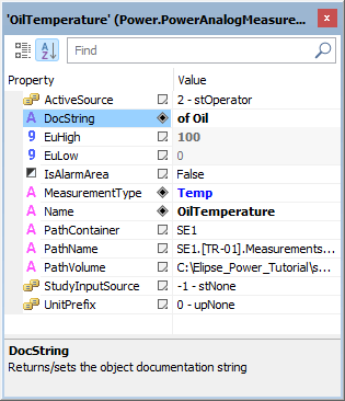
DocString property of Oil Temperature
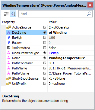
DocString property of Winding Temperature
Notice that, with this solution, the Temp standard becomes available for any temperature measurement, allowing users to specify, in the measurement, where this value is measured.
14.Open the SE1_Screen and create XPowerDisplay objects near Transformer TR-01, linking each one of them with its respective Measurement.
15.Execute the application and test this new functionality.