To communicate Elipse Modbus Simulator with E3, a Modbus.dll Driver is used, available for download at www.elipse.com.br.
1.Right-click the Server Objects - Drivers and OPC item and select the Insert I/O Driver in - E3Training.prj option.
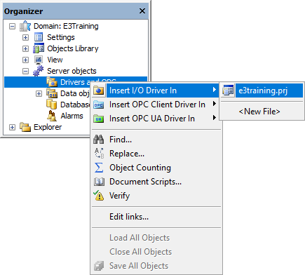
Insert I/O Driver option
2.Select the Driver file (Modbus.dll) on the dialog box to select files.
3.On the Modbus tab, select the Modbus TCP protocol in the Modbus Mode option and, in the Data Address Model Offset option, select the Data is address from 1 item, because the first address on the Simulator is 1 (one).
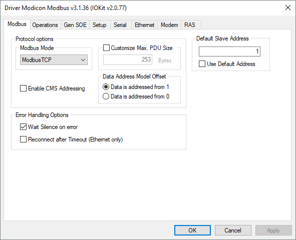
Modbus tab
4.On the Operations tab, check the code for reading and writing operations needed for reading PLC registers.
•Registers: Reads analog values (Word) by using the Modbus 03 function (Read Holding Registers) and writes by using the Modbus 06 (Preset Single Registers) or Modbus 16 (Preset Multiple Registers) functions. The operation 01 executes a Modbus 03 (Read) reading and a Modbus 16 (Write) writing of Word-type (Data) values
•Coils: Reads digital values (Bit) by using the Modbus 01 function and writes by using the Modbus 05 function (Force Single Coil). There is no operation with this configuration on the default list, so users must add a new one
5.On the right side of Operations tab, click Add to create operation 08. Select the item 01 on the list of items of the Read option and, in the Write option, the item 05.
6.The list of available operations is displayed on the next figure.
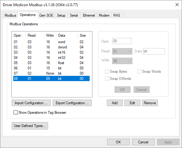
Operations tab
7.These operation codes are used later when configuring I/O Tags:
•Coils: Operation code 08
•Registers: Operation code 01
8.On the Setup tab, configure the time this Driver waits for a response from a device in the Timeout option, such as 1000 ms. Select, on the Physical Layer option, the Ethernet item.
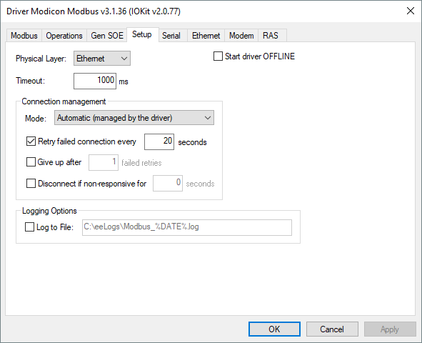
Setup tab
9.After selecting a physical layer, all other tabs are disabled, and users only need to configure the selected interface. On the Ethernet tab, type the IP address of the computer executing the Simulator. If the Simulator is on the same computer of E3, type "127.0.0.1".
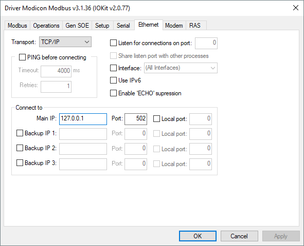
Ethernet tab
10.In the Port option, type the number of the communication port. For example, type "502" to access the first PLC of the Simulator.
11.After finishing this configuration, click OK.
12.If users need to configure this Driver again, right-click the Driver object and select the Settings item.
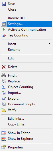
Settings menu