Before using SOE Collecting Tags, users must prepare the PLC by creating a DB Table (V area) and developing a programmable logic compatible with all SOE collecting procedures developed for this Driver.
Table of SOE Events
This table aims to configure the size of the event buffer and manage their input and output in a circular buffer routine. This table is constantly updated by both the PLC and the Siemens MProt (MPI/PPI/ISO-TCP) Driver.
The Table of SOE Events must contain registers on control and storage of events, based on the data structure described on the next table.
Data structure
Address |
Description |
Data Type |
|---|---|---|
0.0 |
|
STRUCT |
+0.0 |
Table status |
WORD (unsigned 16-bit) |
+2.0 |
Recording pointer |
WORD (unsigned 16-bit) |
+4.0 |
Acquisition status |
WORD (unsigned 16-bit) |
+6.0 |
Maximum limit of items on the circular buffer |
WORD (unsigned 16-bit) |
+8.0 |
Circular buffer |
ARRAY[1..n] (limit of user-defined items) |
+0.0 |
|
STRUCT |
+0.0 |
TIMESTAMP_LOLO (year) |
WORD (unsigned 16-bit) |
+2.0 |
TIMESTAMP_LOHI (day and month) |
WORD (unsigned 16-bit) |
+4.0 |
TIMESTAMP_HILO (hour and minute) |
WORD (unsigned 16-bit) |
+6.0 |
TIMESTAMP_HIHI (second and millisecond) |
WORD (unsigned 16-bit) |
+8.0 |
Value of event type 1 (one) |
Event's data type (user-defined) |
+n.0 |
Value of event type 2 (two) |
Repeats the same data type |
+n.0 |
Value of event type 3 (three) |
Repeats the same data type |
+n.0 |
Value of event type n |
Repeats the same data type |
=n.0 |
|
END_STRUCT |
=n.0 |
|
END_STRUCT |
Description of Event Control Registers
•Table Status: It must be kept exclusively by the PLC, indicating the number of events available for reading in the circular buffer. It must be updated by the PLC whenever new events are added to the circular buffer, or after completing the collecting of events by the application, which can be detected when Acquisition Status changes
•Recording Pointer: It must be kept exclusively by the PLC, indicating the index, starting at 0 (zero), of the position where the next event must be inserted. The index must be incremented by the PLC whenever a new event is inserted in the circular buffer, then returning to index 0 (zero) after reaching the maximum limit of the circular buffer
•Acquisition Status: It must be kept by the PLC and by the Siemens MProt (MPI/PPI/ISO-TCP) Driver, indicating the number of records already read at every transaction. After each collecting, the Siemens MProt (MPI/PPI/ISO-TCP) Driver writes to this register the number of events that it could read. When detecting this change, the PLC must immediately subtract this value written by the Siemens MProt (MPI/PPI/ISO-TCP) Driver from the Table Status and then reset the Acquisition Status
•Maximum Limit of Items of the Circular Buffer: A constant value that specifies the maximum limit of events to store in the circular buffer before the pointer moves back to index 0 (zero). It must contain exactly the limit value of the Array resized for events of the circular buffer
Description of Event Storage Registers
•TIMESTAMP: Time when the event occurred
•Event Value: Value of the occurred event, which can be composed by one or n values, (all with the same data type, in which they are grouped together for the same TIMESTAMP generated when an event occurs
TIMESTAMP format
A TIMESTAMP is represented by four Words, according to the data structure described on the next table.
Data structure
Word |
Content |
Range |
|---|---|---|
0 |
Year |
Between 0 (zero) and 65535 |
1 |
Day and month |
ddddddddmmmmmmmm |
2 |
Hour and minute |
hhhhhhhhmmmmmmmm |
3 |
Second and millisecond |
ssssssmmmmmmmmmm |
•The first Word contains an integer value referring to a year
•The second Word is divided into a high byte to represent a day and into a low byte to represent a month
•The third Word is divided into a high byte to represent hours and into a low byte to represent minutes
•The fourth Word uses the six highest bits to represent seconds and the 10 lowest bits to represent milliseconds
Acquisition Procedure
The PLC must start inserting events in ascending order, starting from table's base address, referring to the beginning of the circular buffer. At every new event inserted, the recording pointer must be incremented, starting to point to the next buffer's available address.
This Driver performs an event reading from the oldest one to the newest one. The starting address for reading is calculated by this Driver using the value of Recording Pointer and Table Status.
If the number of available events is greater than the maximum allowed in a single protocol's communication frame, this Driver performs multiple block readings, updating the value of Acquisition Status at the end of the process with the total amount of events read.
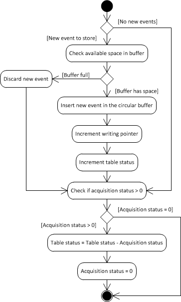
When detecting that this Driver wrote a value greater than 0 (zero) to Acquisition Status, the PLC must immediately subtract the value of Acquisition Status from the value of Table Status and then reset Acquisition Status.
The PLC can insert new events on the table during PLC's acquisition process, as long as there is no overflow in the circular buffer, then incrementing Table Status.
The next figure presents a flowchart, as a UML Activity Diagram, with a suggested implementation for this PLC logic.

SOE flowchart